AEROSPACE TECHNOLOGIES
Your browser is not supported.
For the best experience, please access this site using the latest version of the following browsers:
By closing this window you acknowledge that your experience on this website may be degraded.
Understanding FMS Navigation Procedures: ARINC 424 Path Terminators
What’s the FMS Doing? How the FMS Processes Navigation Procedure Data
While pilots strive for expertise on their aircraft systems, the FMS seems to remain a mystery. This article will help explain how some navigation procedures are coded and processed by the FMS. We’ll also address procedure types that seem to provoke questions and through explanation give readers a chance to better understand what their FMS is “doing”.
What You Will Learn in This Article
- How Flight Management Systems (FMS) Interpret and Process Navigation Procedures: Gain clarity on how FMS software translates complex navigation data, including the role of ARINC 424 standards and the process from procedure design to database encoding.
- Key Path Terminators Used in FMS-Driven Procedures:Understand the eight most common ARINC 424 path terminators (such as VA, CA, DF, CF, TF, VM, VI, FA), their operational logic, and how they affect aircraft routing and pilot decision-making.
- Practical Implications for Pilots and Procedure Designers:Learn how FMS limitations and procedure coding impact flight guidance, sequencing, and manual interventions, enabling more informed use of FMS during departures and transitions.
FMS Background
The FMS is designed to process flight plan waypoints as they are defined by ARINC 424 (Navigation System Database Specification). This has led to a very reliable navigation system over a period of many years. So, while airport terminal procedures grow in complexity over time, the FMS needs to accommodate change while utilizing existing software coding and specifications.
When procedures are designed, typically using PANS-OPS or TERPS, the lateral and vertical paths are defined in a manner that will provide obstacle protection. Once the procedure has been designed and approved it can then be encoded. The navigation database in any Honeywell FMS is developed using data that is supplied by a Type I Data Supplier. These suppliers collect navigation data from various official state sources around the world. The data is then encoded using ARINC 424 standards and is distributed to various users such as FMS manufacturers. The FMS manufacturers, like Honeywell, are considered a Type II data supplier, as the encoded data received must be translated into a language that can be read by the FMS.
FMS Leg Types
The waypoints loaded into a terminal procedure are linked together using ARINC 424 Path and Terminator criteria, often referred to as leg types. The two elements of the Path and Terminator prescribe the way in which a path is to be flown and how the path is to be terminated. For example, in “Direct to a Fix” or “DF” leg type, the direct is the Path and the fix is the Terminator.
There are several path terminators that are consistently used in procedure design. This review will cover the following eight (8) of the twenty-three (23) different path terminators by walking through a few example departure procedures.
- VA – Vector or Heading to an Altitude
- CA – Course to an Altitude
- DF – Direct to a Fix
- CF – Course to a Fix
- TF – Track to a Fix
- VM – Course to a Manual Termination
- VI – Heading to Intercept
- FA – Fix to an Altitude
Figure 1 below shows the WELLY 3 RNAV Departure procedure (KPBI, West Palm Beach) and will be used to help describe our first six (6) Path Terminators (VA, CA, DF, CF, TF, and VM).
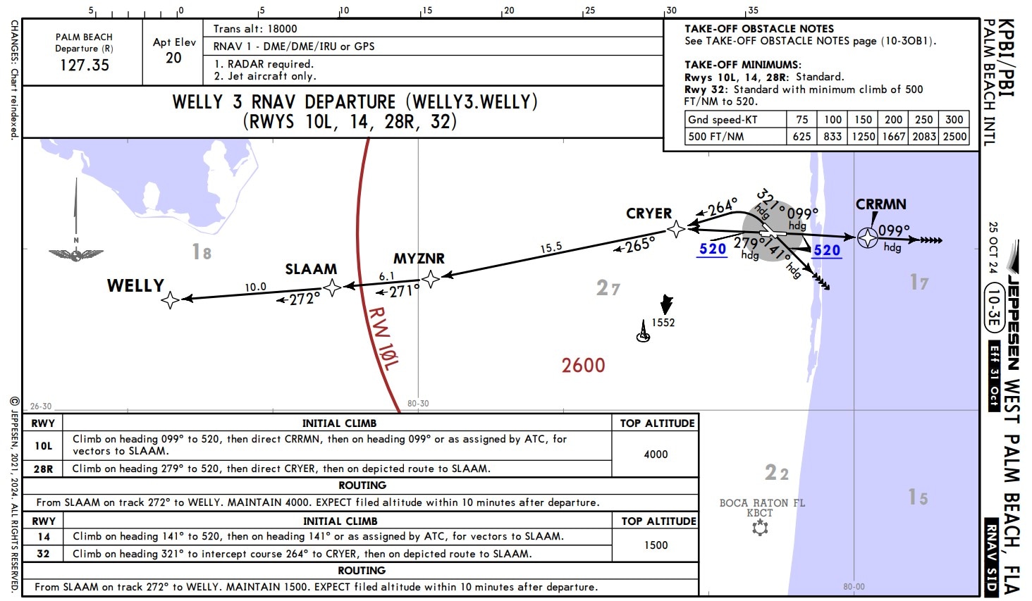
Figure 1. WELLY 3 RNAV DEPARTURE (NOT for Navigation)
Vector or Heading to an Altitude (VA) / Course to an Altitude (CA)
As seen in the above image, there are four runway transitions that could be loaded into the FMS. In this first example, we will review the runway 28R transition. Looking at the planview and the textual description (both in Figure 1) of the procedure, departing from runway 28R, the aircraft is to fly a heading of 279 degrees until reaching 520 feet, then direct CRYER. The procedure designer wants the aircraft to reach the specified altitude prior to making any turns or course changes.
This introduces the first of two Path Terminators, the “VA” or Vector to an Altitude (Figure 2) and “CA” or Course to an Altitude (Figure 3). In the “CA”, note the addition of an amber waypoint symbol. This is because the “VA” uses a simple Vector or Heading flown, while in contrast the “CA” uses a defined Course. To fly a course there must be a starting point that defines exactly where the course will be flown. There are certain FMS types that are not able to process a “VA”, so it will be converted to a “CA” by the navigation database compiling tool.
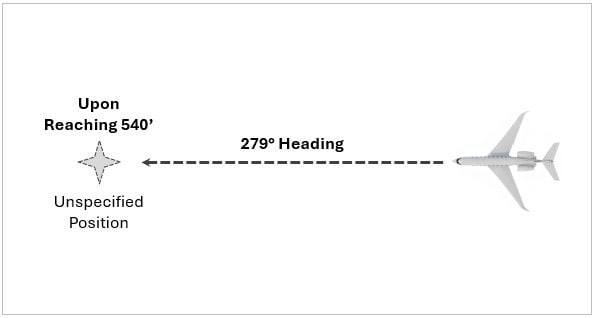
Figure 2. VA (Vector to an Altitude)
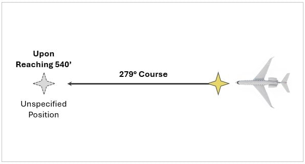
Figure 3. CA (Course to an Altitude)
When the procedure is loaded into the FMS (Figure 4), it displays the waypoint *ALT with a course of 279 degrees and the vertical constraint of 520. The waypoint name, *ALT, informs the pilot that waypoint sequencing will occur once the altitude constraint has been met.
Figure 4. Departure Legs on FMS Flight Plan (Runway 28R)
Direct to a Fix (DF) / Course to a Fix (CF)
Continuing with the departure procedure for Runway 28R, after *ALT the procedure designer wants the aircraft to proceed directly to CRYER. Because the previous Path Terminator did not have a specified geographic location where it would terminate, due to variable aircraft climb performance, the navigation data must now command a new calculation to steer the aircraft to the desired waypoint. This will be accomplished by the FMS using a “DF” or Direct to a Fix path terminator.
As mentioned before, the calculated course into CRYER while on the ground awaiting takeoff was 278 degrees (Figure 4). But in flight, after sequencing the altitude waypoint, the new course calculated to CRYER may be different. This is because the actual distance to reach the 520’ altitude, and any crosswind drift, may lead to differences from the precalculated distance (see, Figure 5).
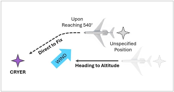
Figure 5. DF (Direct to a Fix)
Track to a Fix (TF)
Subsequent remaining legs on the same departure procedure are more straight-forward, using Track to a Fix to connect waypoints such as CRYER, MYZNR, SLAAM, and WELLY. The Track to a Fix or “TF” path terminator (Figure 6) simply tells the FMS to connect one fix to the next by using a great circle route. It is the simplest of path terminators and is very commonly used to link fly-by waypoints together, particularly enroute. For example, airway construction is typically straightforward as it simply links waypoints together to create a defined route using “TF” (track to a fix) legs. Procedure designers can position waypoints using latitude/longitude and use “TF” path terminators thus allowing the FMS to connect them together.
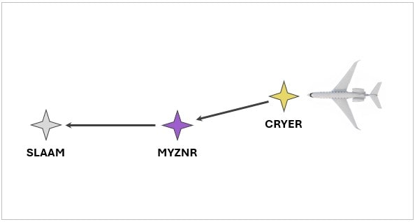
Figure 6. TF (Track to a Fix)
Course to a Manual Termination (VM)
A commonly used path terminator in departure procedures, but maybe least understood, is the “VM”, or Course to a Manual Termination.
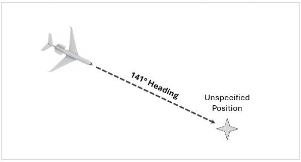
Figure 7. VM (Course to a Manual Termination)
For example, using the same departure procedure we have been discussing, but now departing West Palm Beach on Runway 14, pilot instructions are to “climb on heading 141° to 520’, then remain on heading 141°, or as assigned by ATC for subsequent vectors to SLAAM”.
The path terminator in the first part of the procedure (discussed previously) is a heading to an altitude (“VA”) that will be used to command the aircraft until reaching the encoded altitude of 520 feet. Once there, the aircraft should fly a heading of 141 degrees and await further instructions. This introduces the “VM” path terminator (Figure 7). As described by ARINC 424, the VM leg “defines a specified heading until a manual termination.” The intent of the VM in this instance is to place the aircraft on a heading and allow ATC to provide guidance once the aircraft is stabilized on the final climb segment.
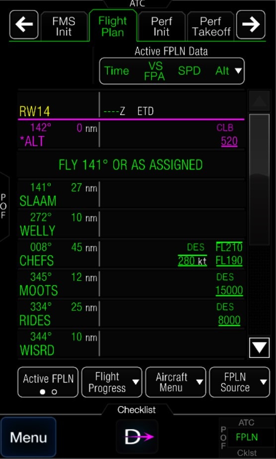
Figure 8. Departure Legs on FMS Flight Plan (Runway 14)
Because the FMS was designed to fly tracks and not headings, the “Course to a Manual Termination” will be utilized by the FMS as shown in Figure 8, but will not be capable of flying the heading in the LNAV flight guidance mode. The FMS may command a turn to the heading and then disconnect lateral navigation (LNAV), reverting to basic ROLL mode. This will force the pilot to resume control of the lateral guidance providing the steering commands by some other means. Therefore, if a “FLY XXX° OR AS ASSIGNED” is seen on the FMS, the pilot should anticipate flight guidance reversion to a basic mode.
Heading to Intercept (VI) and Fix to an Altitude (FA)
The final two path terminators, “VA” and “FA”, will be further illustrated below using the Deer Valley airport in Phoenix to provide a great example of a procedure that appears straight forward but becomes quite complicated when analyzing various scenarios. This specific example will look at the Deer Valley Three Departure using Runway 25L (Figure 9).
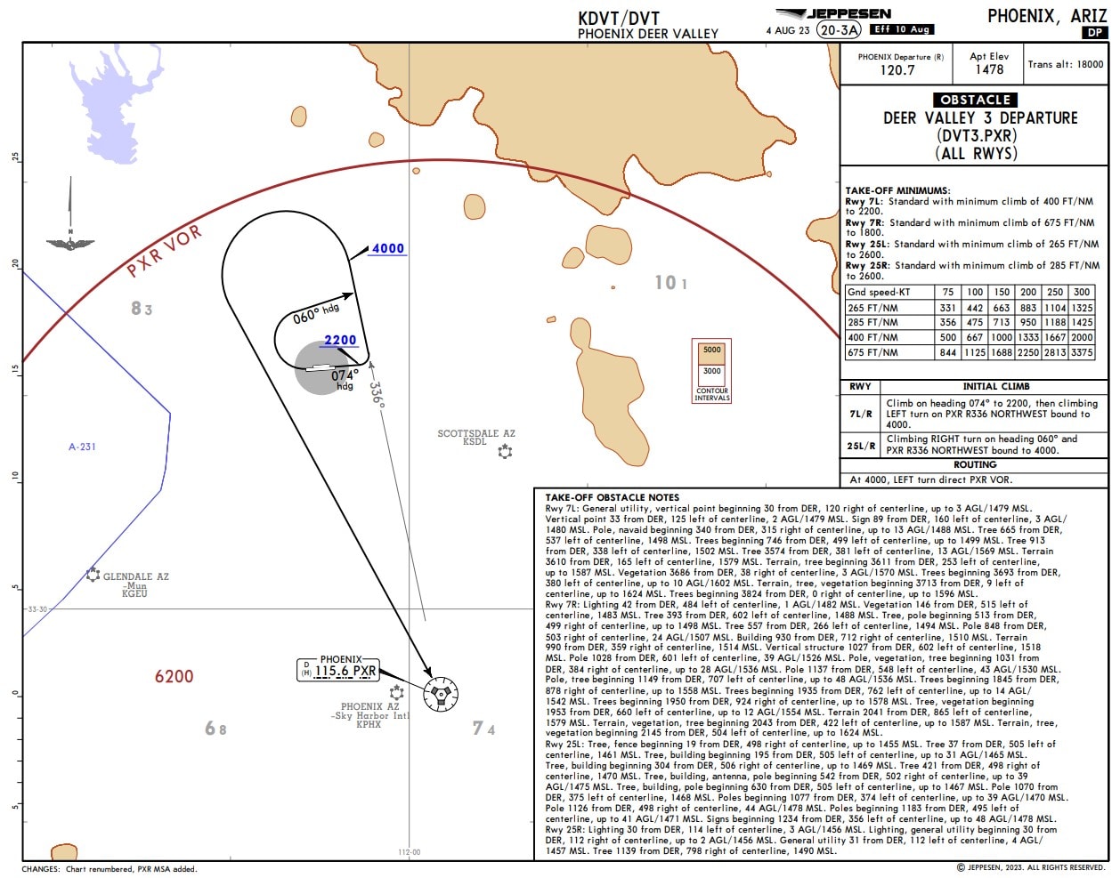
Figure 9. KDVT DEER VALLEY 3 DEPARTURE (NOT for Navigation)
The departure procedure will guide the aircraft from the runway into a series of turns that will ultimately intercept the Phoenix, PXR 336° radial. Upon reaching the radial after the first right turn, there is a left turn to the northwest followed by another left turn direct to the PXR VOR, but only after reaching 4,000 feet first.
Immediately after takeoff, “CA” (Course to an Altitude) is used in the first leg with a specified course of 254 degrees until reaching 1,880 feet (as standard practice, approximately 400 feet above the airport elevation). Upon reaching 1,880 feet the FMS will then sequence from the “CA” leg to making the “VI” (Heading to Intercept) leg active. ARINC 424 defines “VI” (Heading or Vector to an Intercept) as a leg that uses a “specified heading to intercept the subsequent leg at an unspecified position”. See Figure 10.
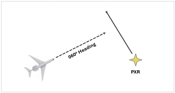
Figure 10. VI (Heading to an Intercept)
Note the turn direction, and the reverse video R in Figure 11, specifying the right turn. The FMS uses this to command a right turn to a 060° heading.
The “VI” leg will terminate and sequence to the “FA” (Fix to an Altitude) leg upon intercepting the PXR 336 radial, this is further illustrated in Figure 11, below. The “FA” leg is described as a “specified track over ground from a database fix to a specified altitude at an unspecified position”.
The “FA” leg will now be the active and the aircraft will be flying outbound on the PXR R-336 until reaching 4,000 feet. Upon reaching a distance along that radial which is unspecified, the “FA” leg will sequence and the “DF” (Direct to a Fix) with a left turn (with reverse video L) will become the active waypoint. Once the aircraft reaches the PXR VOR the departure procedure will be complete and the aircraft will then join the enroute structure with a Track to Fix (“TF”) leg to PGA.
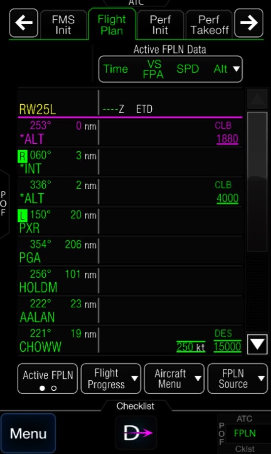
Figure 11. Departure Legs on FMS Flight Plan (Runway 25L)
Departure procedure coding can be quite complicated; however, with a general understanding of procedure design intent and basic ARINC 424 path terminators, pilots can be more confident in what the FMS will do next.
Let's Connect!
The latest news in aerospace backed by expert insights
Sign up to receive the latest news about events, special offers and related topics via email and other forms of electronic communication.
